Page 14 of 18

Import/Export Maximo ImageLib Data via Integration Framework

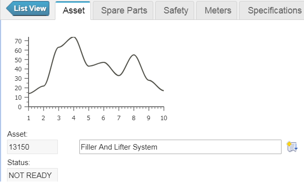
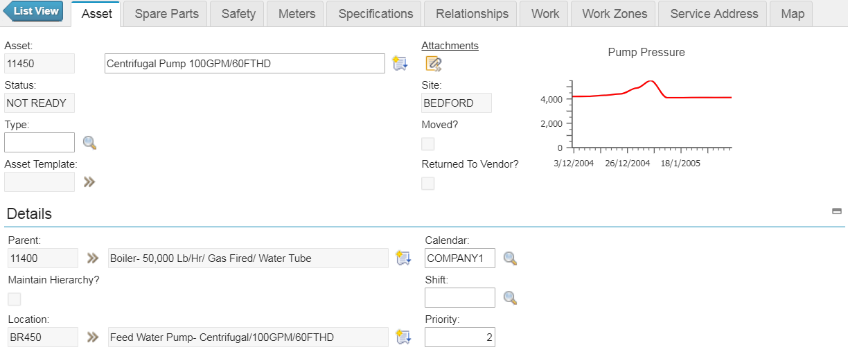
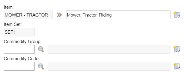
In Maximo, we can upload images as attachments (DOCLINKS) which are stored as files on the server or as “profile” images which are stored as binary data inside the IMAGELIB table. Profile image is quite useful to give the user a quick view of what an inventory item or an asset/location looks like.

While Maximo allows us to upload DOCLINKS attachments via the Maximo Integration Framework (MIF), uploading images to the IMAGELIB table via MIF is not supported out-of-the-box. Therefore, to upload images, we can only do it manually one by one via the Maximo UI.

For bulk loading, if we have access to the DB server, we can write a stored procedure to read the files and import binary data directly to the database. There are two scenarios I had in the past in which this
approach doesn’t work

  • When we built mobile apps and wanted to upload data to IMAGELIB. In that case, my teammate extended a REST handler class to achieve this requirement.
  • When we needed to bulk upload images, the client did not give us access to the database

To address this requirement, we can extend the process classes of object structure (OS) to encode/decode binary data into Base64 string to deliver the data via XML or JSON format. Since this processing is done on object structure, it will support both application Import/Export and sending/receiving binary data via the integration framework’s MEAWEB API or JSON API.

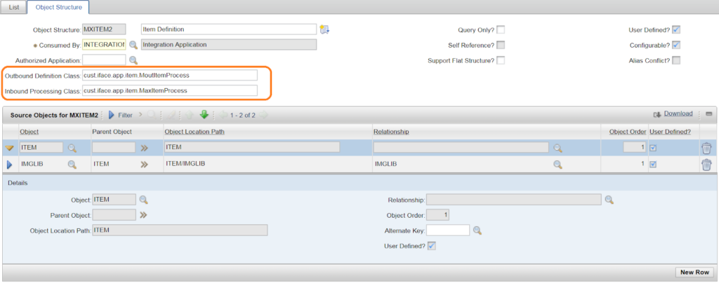
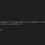
To encode binary data to Base64 text string before exporting OS data, we can extend MicSetOut.class and associate it to the OS by specifying the class’s path in the “Outbound Definition Class” field. Below is the sample Java code which exports Item master data with Image:

To decode base64 string back to binary data before storing it to IMAGELIB table, we can extend the MicSetIn.class and associate it to the OS by specifying the class’s path in the “Inbound Processing Class” field. Below is the sample Java code:

Once we have the customized classes in place, it is possible to Export/Import ImageLib data using XML format or via web services. It is also quite easy to write a simple Excel/VBA program to bulk upload images via MIF without the need to have direct access to the DB server. But these are different topics and perhaps, I’ll provide examples in other future posts.

Federated MBO / JSON Resource – Filling the gap between Maximo and IoT

What is a Federated MBO?

Recently I got some time to explore the new Federated MBO feature. I like it a lot because it is simple to configure and quite powerful. Of course, prior to Maximo 7.6, the same functionality can be done with Java programming, but with this new feature, it is so easy to incorporate data from external systems into Maximo business logic and make a seamless experience to the end-users.

Basically, Federated MBO allows you to link an API from an external system and make it looks like a standard object in Maximo and treat it like other standard Maximo objects such as displaying data on GUI or setting up workflow conditions or writing automation script against it. The key difference here is that data is not stored inside Maximo database but queried from the API on-the-fly when the object is accessed.

Use Cases

I can immediately think of several applications that are enabled by this feature:

  • Integrate with Data Historian/SCADA: to display real-time operation conditions of assets. It is always beneficial for the asset managers to know the current conditions of the assets when planning works. Traditionally, operation conditions of critical assets can be imported/synchronized into asset meters for conditional monitoring PM or analytical reports. But it is not real time data. Generally, we don’t import every meter reading collected into Maximo. It will fill-up the database and consume valuable system resource. With this capability, we will only query data of a specific asset or location directly from an external system and don’t store it in the DB. However, we still can interact with the data as part of Maximo functionality which is a distinct advantage over other methods such as embedding the web page of an external system inside Maximo or directing user to a different web application
  • Integrate with security access systems: to display in real-time the current whereabouts of a worker. This could help with work planning and coordination activities.
  • Integrate with external service: to verify ID, Certificates etc. for the labour self-registration process.
  • Integrate with weather service to assist work planning process. For example, Maximo will warn the planner when planning to work if extreme heat, high UV, or heavy rain is forecasted. This allows them to plan the work on a different date or prepare proper PPE equipment to the workers. The same can be done if we deploy sensors to report temperature, noise level, humidity etc. on certain work locations.

Implementation

To demonstrate how the Federated MBO feature works, below is an exercise I did with OpenWeatherMap API. This API provides free access to 5-day weather forecast, UV Index forecast, and Air Pollution. In this example, I will link the UV Index forecast API and make it available as an MBO. When the user set a Scheduled Start Date, if UV Index is forecasted to be higher than 7, Maximo will display a warning message to remind the planner.

Step 1: Register OpenWeatherMap API account, and retrieve data on browser

  • Go to OpenWeatherMap.org to register a free account.
  • Sign-in with your new account, go to Account home page, open the “API keys” tab and copy your API key to use it to access the API.
  • Paste the following link into a new browser tab, replace the XXX with your API key, you should be able to retrieve JSON data of the UV Index forecast for the next 8 days as shown in the image below 
http://api.openweathermap.org/data/2.5/uvi/forecast?lat=-33.8688&lon=151.2093&cnt=7&appid=XXX
Test the OpenWeatherMap URL in browser
  • If you couldn’t retrieve the data, go to the site’s API document to read the instructions. It might have been updated. The OpenWeatherMap’s API syntax is very simple.

Step 2: Create a JSON Resource in Maximo

  • In Maximo, go to the Integration \ JSON Resource application. Under the More Actions menu, click Create JSON resource to start the wizard
  • Create a new Resource
    • Resource: OW_UVI
    • Resource Usage: OBJECT
    • Resource Type: REST
    • URL: <copy/paste the URL in the previous step above>
  • Note: for simplicity, we hardcode the latitude/longitude of the location in the URL. Once it works, you can dynamically populate the values from the main object by putting the field name inside a bracket such as:
    lat={LOCATIONS.LATITUDE}&lon={LOCATIONS.LONGITUDE}
  • Click Next 
  • Copy/Paste the sample JSON data we retrieved in previous step from OpenWeatherMap into the JSON Data text area. This allows Maximo to parse the data structure returned from the API for the next step
  • For Parent Object, enter “WORKORDER”. This will create a relationship on the “WORKORDER” object to point to the new JSON object “OW_UVI” we are creating
  • Click Next to proceed to the next screen. This screen summarizes how Maximo parsed and construct new MBO structure from the sample data provided.
  • Leave the default value, click Process to finish.

Step 3: Test the new JSON Resource

  • In the Database Configuration application, open the new OW_UVI object it just created for us. It also added a relationship OW_UVI in the WORKORDER object to link to this new mbo.
  • To check if our JSON resource can query data from the API correctly, use Application Designer, add a Table to anywhere, such as the “Map” tab. Open properties of the table, put OW_UVI as the relationship of the table. Add two columns and assign the DATE_ISO and VALUE field to the two columns. 
  • Open the Work Order Tracking app, open any work order, the table will display some UV forecast data:

Step 4: Create a warning using Automation Script

  • Open the Database Configuration app, choose Action > Messages to open the Message dialog. Create a new Warning Message:
    • Message Group: WOTRACK
    • Message Key: HighUVI
    • Value: High UV Index is forecasted for the scheduled date. Ensure proper sun protection PPE has been planned.
  • Note: the Message Group and Message Key fields are case-sensitive. Thus, in automation script, we should use the exact case in order for the message to be displayed
  • Open Automation Script app, Create an Attribute Launch Point:
    • Launch Point: SCHEDSTART
    • Object: WORKORDER
    • Attribute: SCHEDSTART
    • Event: Validate 
  • Click Next to the next screen, give the script a name such as Check_UVI choose Python as language
  • Click Next. Copy/Paste the following source into the Source code text area, then click Create to finish creating the script
  • In this script, I compare and identify if the Scheduled Start Date is in the next 8 days, and if the UV Index is higher than 7. If this condition is met, Maximo will display the warning we created above.

Extras

With Maximo 7.6, we can setup to assign Service Address to Location with coordinate of the location. When a Work Order is created against a location, it will inherit the coordinate of the location. We can use it to fill into the parameter of the API request, and retrieve the actual forecast of the Work Order’s location.  If you’ve read my previous post on creating custom chart control, we can also modify the app to display UV Index forecast in a chart for visualization. A planner after receiving the warning can then open the “Map” tab to see the location of the work, and see the UV Index forecast on a chart to determine what day is better to carry out the work.

I hope you have fun with this new Maximo feature. If you can think of any creative application using this feature to make Maximo better, please suggest by leaving me a comment. I would love to try it out

Blanket Contract and Procurement in Maximo

A friend of mine who has experience with SAP asked whether Maximo can handle a “Blanket PO” process similar to SAP. I sent him my answer based on the scenario and requirement he provided and think it is probably worth posting here as some other people may find it interesting:


In the Purchase Contracts application, we can create a new Purchase Contract of type “Blanket”  and give it a Maximum Amount say $1.5M. Some companies call it “Budget” because this is the limit a user can use to release Purchase Orders (PO). This is called “Release PO” in Maximo, but I saw many of my clients in the energy sector refer to it as “Call-Out” or “Work order”. Blanket Contract is also sometimes referred to using different terms such as Frame Contract, Framework Contract, or Price Contract. I mention this because the “Work Order” PO can easily be confused with normal maintenance Work Order, and “Price contract” in this case can easily be confused with the “Price Contract” type in Maximo which works a bit differently.

 
To create a Release PO, on the Contract app, we use the “Select Action >> Create Release PO”, and then select the contract items we want to procure. We can choose not to select any existing contract item, generate an empty PO, and add service/material items to the PO lines later. The total amount of the PO will still be counted against this Contract.
 
 
GL Account is specified in PO, not in Contract because the contract is an agreement between the operating company and a 3rd party vendor; it is generally to define terms and conditions and set a fixed price for certain goods or services. When the good or service is actually ordered (by issuing a Release PO), we will have a better idea of where and how it is used (on what project/work order or on what location/asset/cost centre?).
 
 
In the Purchase Order application, we can distribute the cost of each line item to charge against different cost centres or GL accounts for more detailed financial reporting. To do this, we can select a line and click on the “Distribute Cost” button and specify the cost and GL account that we want to charge against. This information will also be copied to the Invoice when creating an Invoice record so that accountants can determine what expenses will be recorded against what accounts.
 
 
The rest of the steps are similar to the standard procurement process: we can receive material/service using the Receiving application, and we can create an Invoice against the receipts. (In the Receiving application, even with the latest version, Maximo still treats each line item received as a separate transaction, I prefer IBM to introduce an app that groups all items received each time into one Receipt header record which can be used to enter details like the receiver, inspector, and actual receipt date).
 
 
If Maximo is integrated with the Finance system, generally, items in an approved PO are posted as a “commitment” transaction, items received into inventory are posted as “accrual”, and items/services purchased against an Asset/Location, Work order, or simply a GL, which are referred to as “Direct Issue” item in Maximo, are posted as “expense”, and Invoice is posted as “payable”, “tax”, and “expense” transactions.
 
In the Contract application, we can open a Blanket Contract, and click on “Select Action >> View Release Cost” to see with the original “budget”, how many Release POs have been issued, the total committed amount, the total received, and the remaining of the “budgeted” amount we have left to spend on future release.
 

Maximo custom control (Part IV) – Create a chart control


In the previous posts, we have practised how to create a JSP page, register it as a component, and register a control. We also discussed how to pass properties from the control to its components and use it with conditional UI.
 
In this post, I will provide an example to build a chart control to display meter data
of an asset.


A – First, let’s start by creating our basic control:

  • Create a “customchart.jsp” file with the following lines and place it inside the folder “maximo/ applications/ maximo/ maximouiweb/ webmodule/ webclient/ components”:
  • Register the JSP file as a component by creating a “customchart-component-registry.xml” file and place it inside folder  “maximo/ applications/ maximo/ properties/ registry-extensions”
  • Register a control using the component we just created by creating a “customchart-control-registry.xml” file in the same registry-extensions folder
  • Build EAR file, Deploy, and Start Maximo server. (Note: for a development environment, if you place these files directly to the EAR package in Websphere’s installedApps folder, you only need to restart Maximo server to register the new control and component.  After that, any change to JSP
    file doesn’t need a restart)
  • Export Asset application and edit the application design XML file to add the new control above the Assetnum multipart textbox control:
  • Open the Asset application and we should see our new control with the placeholder text as in the following image:

B – Replace
our placeholder text with a dummy line chart

  • Modify “customchart.jsp” to display a line chart with dummy data, and use the property to resize our control instead of using hard-coded value:
  • Examine the code, you will notice that we use a few variables such as “component”, “dojo” without declaring them. It is because there are commonly used variables and libraries which have been declared or imported in the “componentheader.jsp” file we included when defining our component. You can examine this file to find out about other variables that you can use. One such is the “s” variable, which is an MXSession instance, which I will use later to query data from the Maximo database.
  • Edit our Asset application XML file to specify the size of our custom control by adding the width and height property: <customchart id=”cust_chart_1″ dataattribute=”assetnum” width=”250″ height=”150″ />. 
  • Open the Asset application, and it should show a chart with dummy data as follows:

C –Update “customchart.jsp” display actual meter data:

  • Using the MXSession instance variable “s” to retrieve meter data from the database: MboSetRemote readingsSet = s.getMboSet(“MEASUREMENT”);
  • For the sake of simplicity, I hardcoded the query to display data of the “O-PRESSUR” meter from Asset “11450”. This is standard Maximo Mbo Java code. If you are already familiar with this, you will have no problem handling more complex requirements to display correct information here. (If you are not familiar with Maximo Mbo Java, you can learn the basics from Bruno’s blog)
  • After retrieving the MboSet, we get the meter data and put it into an array in JSON format to pass it to Javascript which is processed at the client side by the browser to feed into our DOJO chart.
  • Below is the full code of the customchart.jsp file:
  • Re-arrange the layout a bit using application designer, we should be able to show the pressure chart of the pump on the main asset screen:

So there it is. I hope this series provides you with basic information to start playing with Maximo custom control and enables you to make Maximo more useful to your organisation or clients.

Maximo custom control (Part III) – Conditional UI with custom properties

In the last exercise, we added new properties to a control, and by doing so, we have a better understanding that the properties of a control are defined inside the <property-list>…</property-list> XML element. We also know how properties are passed from the control level to its components.
 
If you have some experience with Application Designer, you must already know that we can dynamically modify the value of a property using Conditional UI. We can do the same with the custom properties that we recently added.
 
With the two properties: “part1size  and “part2size” added to the multipart
textbox in the previous exercise, let’s configure a simple Conditional UI to demonstrate this capability:
  • Create a new condition using Condional Expression Manager
    with following condition: length( :location ) > 10
  • Use Application Designer to edit the “Location” application
  • Select the “Location” multipart textbox under “Main” tab. Right-click on it to open the Properties dialog of the control
  • Go to “Advanced” tab, then add “READ” to the Signature Option box.
  • Click on “Configure Conditional Properties” button to open the Conditional UI configuration dialog.
  • In the “Configure Conditional Properties”, add “Everyone” security group, then specify the Condition we’ve just created in Conditional Express Manager. Under Property Values – Condition is true, enter two properties:
    • Property: part1size – Value: 15
    • Property: part2size – Value: 35
 
  • By doing this, we tell Maximo to resize the two components of the Multipart Textbox when the “location” field has a length of more than 10 characters.
  • Save the application configuration. Then open Location application, find a Location with “Location” field is shorter than 10 characters, open it, you will see the multipart textbox looks normal. But if we open a location with the “Location” field longer than 10 characters, we will see that the multipart textbox is resized to be a bit longer.


The whole purpose of this exercise is to demonstrate that we
can dynamically modify the appearance of Maximo applications by adding new
properties to a control, then modify the value of the properties based on
specific conditions.
 
In the next post, I’ll provide a more detailed example of how to pass property values from the component to JSP file, and then apply some business
rules to Maximo UI controls using JSP and Javascript.


Maximo custom control (Part II) – Control properties

In my last post, I created a super simple control with just a “Hello World” label. The goal of the exercise is for us to identify the core components of a control. In this post, I’ll continue to expand the exercise so we can better understand Maximo’s controls.
One common requirement is the need to modify the size of the multipart textbox control, usually to increase the size of the first textbox to fully display long ID of an item or asset.
Application Designer doesn’t provide us with an option to modify this.
If we export the application design XML file, and add: size=”40”, we will end up increasing the size of both parts to 40 as shown in the image below:
In our previous tutorial, we now know that this multipart textbox is just a control that has two “textbox” components. Therefore, we can definitely control the size of each component. To do that, let’s edit the “control-registry.xml”:


Find the multipart textbox control by searching
keyword: “
multiparttextbox”. In the <property-list>…</property-list>
element, add two more properties: 

   <property name=”part1size” />
   <property name=”part2size” />
In the <component-list>… </component-list> element, you will find two <textbox> components. For the first <textbox> component, pass the first size property: <textbox size=”@{part1size}” id=”tb” … /> . For the second <textbox> component, pass the second property: <textbox size=”@{part2size}” id=”tb2″ … />


Now open Application Designer, export the application we want to edit the size of a multipart textbox. Edit the application XML file to specify the size of each part to meet the requirement. For example, export Item application, and edit the multipart control of the ITEMNUM field to add two properties: <multiparttextbox dataattribute=”ITEMNUM” part1size=”16″ part2size=”34″ … />


Import the XML file back to Maximo, we will see our control having the size of each part modified accordingly:
In the next post, I’ll discuss how we can leverage this capability to address more complex requirements by dynamically updating properties in run time to change a control’s appearance.
« Older posts Newer posts »